18.2 Terms
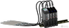
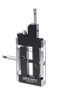
Embodiment Measuring is comparing. In order to measure geometrical deviations, the workpiece surface must be compared with a geometrical ideal feature. But geometrical ideal features cannot be manufactured. Therefore almost geometrical ideal embodiments of geometrical ideal features (e.g. straight lines, planes, circles, cylinders and spheres) are used. They are called embodiments in the following.
The embodiments can be surfaces of measuring devices (e.g. straight edges, measuring tables, solid angles, sliding guides of measuring devices) or can be established by the movements of precision guides (e.g. by rotating the workpiece or the measuring device).
Datum Theoretically exact geometrical reference (such as an axis, plane or straight line) to which toleranced features are related. Datums may be based on one or more datum features of a workpiece; ISO 5459 (see 3.4).
Datum system Group of two or more separate datums used as a combined reference for a toleranced feature; ISO 5459 (see 3.4).
Datum feature Real feature of a workpiece (such as an edge, a plane surface or a hole) that is used to establish the location of a datum; ISO 5459 (see 3.4).
Datum target Point, line or limited area on the workpiece to be used for contact with the manufacturing and inspection equipment, to define the required datums in order to satisfy the functional requirements; ISO 5459 (see 3.4).
Simulated datum feature Real surface of sufficiently precise form (such as a surface plate, a bearing, or a mandrel) contacting the datum feature(s)...