Geometrical Dimensioning and Tolerancing for Design, Manufacturing and Inspection: A Handbook for Geometrical Product Specification using ISO and ASME Standards, Second Edition
The following provides a survey of the most relevant inspection methods.
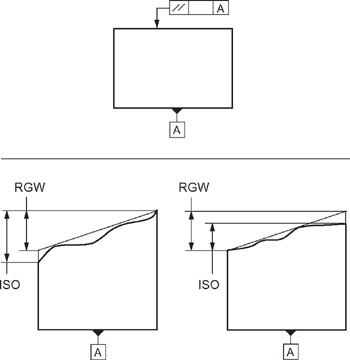
The former East German Standards TGL 39 093 to TGL 39 098 and TGL 43 041 to TGL 43 045 and TGL 43 529, TGL 43 530 provide more detailed descriptions of the same inspection methods. However, it should be noted that tolerances of orientation and location according to TGL 19 080 and according to the former Comecon Standard (in east and middle Europe) ST RGW 301-76 are defined by eliminating the form deviations of the toleranced feature, i.e. deviations of orientation and location do not include deviations of form (Fig. 18.14). This is in contrast to ISO 1101.
In the following the principles of the inspection methods corresponding to ISO 1101 are described.
The deviations of the line of the workpiece surface from an (almost) geometrical ideal reference straight line (embodiment, e.g. established by a straight edge) are measured. The line of the workpiece surface and the reference line are contained in a section plane (Fig. 3.15), or in a projection plane (i.e. a plane onto which the lines and the two parallel planes establishing the tolerance zone are projected) (Figs 3.19 and 3.22).
When the reference line does not intersect (but eventually touches) the workpiece line, the straightness deviation ?