Digital Electronics and Design with VHDL

Objective: In this chapter we conclude our series of design examples using VHDL. This chapter finalizes the study of sequential circuits, which was initiated in the previous chapter. However, while the former showed regular sequential designs, this chapter presents state-machine-based designs. Like the previous chapter, this too is closed with a larger example in which an LCD driver is designed. In the next chapter, the use of VHDL for simulation instead of synthesis will be presented.
Chapter Contents
| 23.1 | String Detector |
| 23.2 | "Universal" Signal Generator |
| 23.3 | Car Alarm |
| 23.4 | LCD Driver |
| 23.5 | Exercises |
We want to design a circuit that takes a serial stream of ASCII characters (Figure 2.12) as input and outputs a 1 whenever the sequence "mp3" occurs. As seen in Chapter 15, this is a typical case in which the FSM approach is helpful.
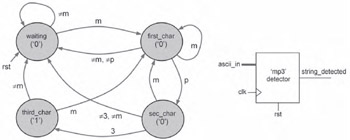
First, the state transition diagram must be drawn, which is shown in Figure 23.1 (this problem is similar to that designed in Example 15.5). There are four states, called waiting, first_char (to which the FSM should move when "m" is detected), second_char (after "m" and "p" have been detected), and finally third_char (after "m," "p," and "3" have been detected). A top-level diagram for the circuit is also included in Figure 23.1.
A VHDL code for this circuit is shown below, which is a direct application of the template seen in Section 19.16. The decimal values...