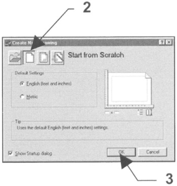
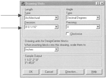
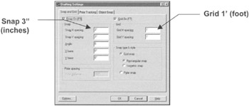
Exercise Workbook for Advanced AutoCAD 2005

The following instructions will guide you through creating a Master feet-inches setup drawing. You will follow the same steps you did in Lesson 3 with a few additional scaling issues.
NEW SETTINGS
Begin your drawing without a template as follows:
Select FILE/NEW .
Select START FROM SCRATCH Box.
Select OK .
Your screen should be blank, no grids and the current layer is 0

Set drawing specifications as follows:
Set UNITS of measurement.
Use FORMAT/UNITS and change the settings as shown below, then select OK.

Set DRAWING LIMITS (size of drawing area).
USE FORMAT/DRAWING LIMITS .
Lower left corner=0 ?0 , 0 ?0
Upper right corner=24, 18. (Notice this is inches, not feet.)
Use VIEW/ZOOM/ ALL to generate the new limits.
Set SNAP AND GRID
Use TOOLS/DRAFTING SETTINGS.

(Set your grids to ON to display the paper size.)
Set PICK BOX size (your preference).
Use Tools/Options/Selection tab.
NEW LAYERS
Create new layers.
Load linetype,
DASHED2
PHANTOM
Assign names, colors, linetypes and plotability. (Use Format/Layer)
| NAME | COLOR | LINETYPE | LWT | PLOT |
|---|---|---|---|---|
| BORDER | RED | CONTINUOUS | .039 | YES |
| CABINETS | CYAN | CONTINUOUS | .016 | YES |
| CONSTRUCTION | WHITE | CONTINUOUS | Default | NO |
| DIMENSION | BLUE | CONTINUOUS | Default | YES |
| DOORS | GREEN | CONTINUOUS | .016 | YES |
| ELECTRICAL | CYAN | CONTINUOUS | .010 | YES |
| FURNITURE | MAGENTA | CONTINUOUS | .016 | YES |
| HARDSCAPE | WHITE | CONTINUOUS | .024 | YES |
| HATCH | GREEN | CONTINUOUS | Default | YES |
| HIDDEN | MAGENTA | DASHED2 | Default | YES |
| MISC | CYAN | CONTINUOUS | .016 | YES |
| OBJECT | RED | CONTINUOUS | .024 | YES |
| PLUMBING | 9 |