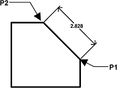
Exercise Workbook for Beginning AutoCAD 2007

Lesson 19

LEARNING OBJECTIVES

After completing this lesson, you will be able to:

  1. Dimension objects that are on an angle.

  2. Draw a Leader.

  3. Draw a line with an arrow (no text)

  4. Add symbols such as: diameter, plus or minus and degree to text.

  5. Pre-assign a prefix or suffix to a dimension.

ALIGNED DIMENSIONING

The ALIGNED dimension command aligns the dimension with the angle of the object that you are dimensioning. The process is the same as Linear dimensioning. It requires two extension line origins and placement of text location. (Example below)

  1. Select the ALIGNED command using one of the following:

    • TYPE = DIMALIGNED or DIMALI or DAL

    • PULLDOWN = DIMENSION / ALIGNED

    • TOOLBAR = DIMENSION

    Command: _dimaligned

  2. Specify first extension line origin or

  3. Specify second extension line origin: select the second extension line origin (P2)

  4. Specify dimension line location or [Mtext/Text/Angle]: place dimension text location

    Dimension text = the dimension value will appear here

LEADER

The LEADER command is primarily used to add a note to an object. A Leader s appearance is very similar to a Radial dimension but a Leader should not to be used for Radial dimensioning. A Leader allows you to type a note at the end of the hook. (Note: Leader and Qleader are the same command)

If associative dimensioning is turned on with DIMASSOC, the leader start point can be associated with a location on an object. If the object is relocated,...

UNLIMITED FREE
ACCESS
TO THE WORLD'S BEST IDEAS

SUBMIT
Already a GlobalSpec user? Log in.

This is embarrasing...

An error occurred while processing the form. Please try again in a few minutes.

Customize Your GlobalSpec Experience

Category: Angular Contact Bearings
Finish!
Privacy Policy

This is embarrasing...

An error occurred while processing the form. Please try again in a few minutes.