Introduction to AutoCAD 2006 2D and 3D Design

To introduce methods of constructing drawings of two types orthographic projection and isometric drawings.
Orthographic projection involves viewing an article being described in a technical drawing from different directions from the front, from a side, from above, from below or from any other viewing position. Orthographic projection often involves:
The drawing of details which are hidden, using hidden detail lines;
Sectional views in which the article being drawn is imagined as being cut through and the cut surface drawn;
Centre lines through arcs, circles, spheres and cylindrical shapes.
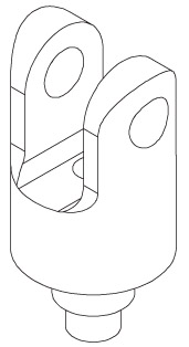
Taking the solid shown in Fig. 7.1, construct a three-view orthographic projection of the solid:
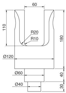
Draw what is seen when the solid is viewed from its left-hand side and regard this as the front of the solid. What is drawn will be a front view (Fig. 7.2).
Fig. 7.2: The front view of the solid
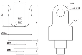
Draw what is seen when the solid is viewed from the left-hand end of the front view. This produces an end view. Fig. 7.3 shows the end view alongside the front view.
Fig. 7.3: Front and end views of the solid
Draw what is seen when the solid is viewed from above the front view. This produces a plan. Fig. 7.4 shows the plan below the front view.
Fig. 7.4: Front and