Introduction to AutoCAD 2006 2D and 3D Design

The Chamfer and Fillet tools

The Chamfer and Fillet tools from the Modify toolbar (Fig. 13.36), which are used to create chamfers and fillets in 2D drawings in AutoCAD 2006, can just as well be used when constructing 3D models.


Fig. 13.36: The Chamfer and Fillet tool icons from the Modify toolbar

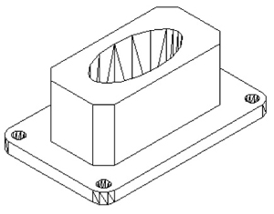
Example Chamfer and Fillet (Fig. 13.39)

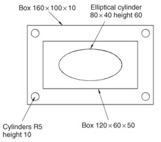
  1. Using the Box and Cylinder tools, construct the 3D model in Fig. 13.37.

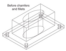
  2. Place in the 3D Views/SW Isometric view (Fig. 13.38). Union the two boxes and with the Subtract tool, subtract the cylinders from the union.


    Fig. 13.37: Example Chamfer and Fillet the model before using the tools


    Fig. 13.38: Example isometric view Chamfer and Fillet the model before using the tools


    Fig. 13.39: Example Chamfer and Fillet

    Note

    To construct the elliptical cylinder:

    Command:_cylinder
    Current wire frame density: ISOLINES = 16
    Specify centre for base of cylinder or [Elliptical] <0,0,0> : enter e right-click
    Specify axis endpoint of ellipse for base of cylinder: 130,160
    Specify second endpoint of ellipse for base of cylinder: 210,160
    Specify length of axis for base of cylinder: 170,180
    Specify height of cylinder or [Center of other end]: 50
    Command:

  3. Click the Fillet tool icon in the Modify toolbar (Fig. 13.36). The command line shows:

    Command:_fillet
    Current settings: Mode = TRIM. Radius = 1
    Specify first object or...

UNLIMITED FREE
ACCESS
TO THE WORLD'S BEST IDEAS

SUBMIT
Already a GlobalSpec user? Log in.

This is embarrasing...

An error occurred while processing the form. Please try again in a few minutes.

Customize Your GlobalSpec Experience

Category: Drilling Units and Tapping Units
Finish!
Privacy Policy

This is embarrasing...

An error occurred while processing the form. Please try again in a few minutes.