Introduction to AutoCAD 2006 2D and 3D Design

Solids of revolution can be constructed from closed plines or from regions.
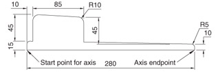
Construct the closed polyline in Fig. 13.18.
Fig. 13.18: First example Revolve. The closed pline
Set ISOLINES to 24.
Call the Revolve tool. The command line shows:
Command:_revolve
Current wire frame density = 24
Select objects: pick the polyline
Select objects: right-click
Specify start point for axis of revolution or define axis by [Object/X (axis)/Y (axis)]: pick
Specify endpoint of axis: pick
Specify angle of revolution <360> : right-click
Command:
Place in the 3D Views/SW Isometric view.
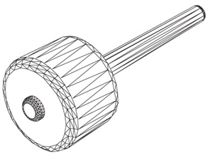
Call Hide.
Fig. 13.19: First example Revolve
Place the screen in the 3D Views/Front view. Zoom to 1.
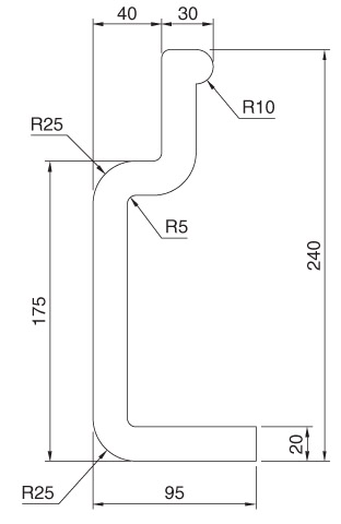
Construct the pline outline (Fig. 13.20).
Fig. 13.20: Second example Revolve. The pline outline
3.Set ISOLINES to 24.
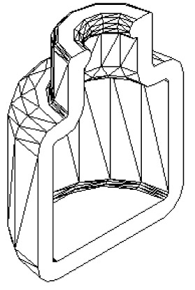
Call the Revolve tool and construct a solid of revolution.
Place the screen in the 3D Views/SW Isometric view.
Call Hide.
Fig. 13.21: Second example Revolve
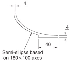
Construct the pline in Fig. 13.22. The drawing must be either a closed pline or a region.
Fig. 13.22: Third example Revolve. The outline to be revolved
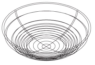
Call Revolve and form a solid of revolution through 180 .
Fig. 13.23: Third example Revolve