Introduction to AutoCAD 2006 2D and 3D Design

2D outlines suitable for 3D models

When constructing outlines suitable as a base for the construction of some forms of 3D model, they can be drawn using either the Line tool or the Polyline tool. If constructed with the Line tool, before being of any use for 3D modelling, the outline must be changed to a region using the Region tool.

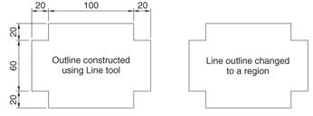
First example Line outline and Region (Fig. 13.4)

  1. Call the Line tool from the Draw toolbar. Construct the outline as shown in the left-hand drawing of Fig. 13.4.


    Fig. 13.4: First example Line outline and Region

  2. Copy the outline to produce a second line outline (right-hand drawing of Fig. 13.4).

  3. At the command line:

    Command: enter pe (Edit Polyline) right-click
    PEDIT Select polyline or [Multiple]: enter m (Multiple) right-click
    Select objects: window the right-hand outline 12 found
    Select objects: right-click
    Convert lines and arcs to polylines [Yes/No] : right-click
    Enter an option [prompts]: enter j (Join) right-click
    12 segments added to polyline.
    Command:

    And the Line outline is changed to a polyline.

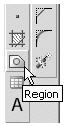
  4. Left-click on the Region tool in the Draw toolbar (Fig. 13.5). The command line shows:

    Command:_region
    Select objects: window the left-hand drawing 12 found
    Select objects: right-click
    1 loop extracted
    1 Region created
    Command:


    Fig. 13.5: The Region tool icon in the Draw toolbar

    And the Line

UNLIMITED FREE
ACCESS
TO THE WORLD'S BEST IDEAS

SUBMIT
Already a GlobalSpec user? Log in.

This is embarrasing...

An error occurred while processing the form. Please try again in a few minutes.

Customize Your GlobalSpec Experience

Category: Audio Processor ICs
Finish!
Privacy Policy

This is embarrasing...

An error occurred while processing the form. Please try again in a few minutes.