Introduction to AutoCAD 2006 2D and 3D Design

Chapter 19: Editing 3D Solid Models: More 3D Models

Aims of this chapter

  1. To introduce the use of tools from the Solids Editing toolbar.

  2. To give examples of the use of the tools from the Solids Editing toolbar.

  3. To show examples of a variety of 3D solid and 3D surface models.

The Solids Editing tools

The tools from the Solids Editing toolbar have already been illustrated on page 174. Examples of the results of using some of the tools from this toolbar are shown in this chapter. These tools are of value if the design of a 3D solid model requires to be changed (edited), although some have a value in constructing solids which cannot easily be constructed using other tools. The Solids Editing tools have no effect when used on 3D surface models.

First example Extrude Faces tool (Fig. 19.3)

  1. Set ISOLINES to 24.

  2. In the UCS *RIGHT* plane construct a cylinder of radius 30 and height 30 (Fig. 19.1).


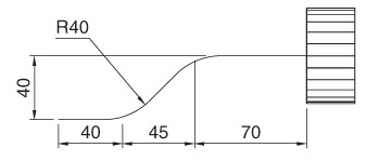
    Fig. 19.1: First example Extrude Faces tool first stages

  3. In the UCS *FRONT* view construct the pline in Fig. 19.1. Mirror the pline to the other end of the cylinder.

  4. In the UCS *WORLD* move the pline to lie central to the cylinder.

  5. Place the screen in the SW Isometric view.

  6. Click the Extrude Faces tool icon in the Solids Editing toolbar (Fig.19.2). The command line shows:

    Command:_solidedit
    Enter a solids editing option [Face/Edge/Body/Undo/eXit]:_face
    Enter a face editing option [Extrude/Move/Rotate/Offset/Taper/Delete/Copy/coLor/Undo/eXit]:_extrude

UNLIMITED FREE
ACCESS
TO THE WORLD'S BEST IDEAS

SUBMIT
Already a GlobalSpec user? Log in.

This is embarrasing...

An error occurred while processing the form. Please try again in a few minutes.

Customize Your GlobalSpec Experience

Category: Solids Granulation and Agglomeration Equipment
Finish!
Privacy Policy

This is embarrasing...

An error occurred while processing the form. Please try again in a few minutes.