Beginning AutoCAD 2006

Placing emphasis on learning by doing, this step-by-step guide provides a detailed exploration of AutoCAD functions required at each stage of producing a 2D drawing.
The line and circle objects so far created were drawn at random on the screen without any attempt being made to specify position or size.
To draw objects accurately, co-ordinate input is required and AutoCAD 2006 allows different 'types' of co-ordinate entry including:
Absolute, i.e. from an origin point
Relative (or incremental), i.e. from the last point referenced.
In this chapter we will use our A3PAPER template file to create a working drawing and use it for future work.
When using co-ordinate input, the user must know the positive and negative directions for both linear and angular input. The two conventions are as follows:
Co-ordinate axes
The X Y axes convention used by AutoCAD is shown in Figure 7.1(a) and displays four points with their co-ordinate values. When using the normal X Y co-ordinate system:
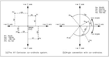
Figure 7.1: Co-ordinate and angle conventions.
a positive X direction is to the right, and a positive Y direction is upwards
a negative X direction is to the left, and a negative Y direction is downwards.
Angles
When angles are being used:
positive angles are anti-clockwise
negative angles are clockwise
Figure 7.1(b) displays the angle convention of four points with their polar co-ordinate values.
If your template file from Chapter 6 is displayed, proceed to step 4.
If AutoCAD is active, then close any existing drawing then menu bar with File-Open and:
| prompt | Select File dialogue box |
| respond |
|