Beginning AutoCAD 2006

Placing emphasis on learning by doing, this step-by-step guide provides a detailed exploration of AutoCAD functions required at each stage of producing a 2D drawing.
All the objects that have been drawn so far have had a continuous linetype and no attempt has been made to introduce centre or hidden lines, or even colour.
AutoCAD has a facility called LAYERS which allows the user to assign different line-types and colours to named layers. For example, a layer may for red continuous lines, another may be for green hidden lines and yet another for blue centre lines.
Layers can be used for specific drawing purposes, e.g. there may be a layer for dimensions, one for hatching, one for text, etc.
Individual layers can be 'switched' on/off by the user to mask out drawing objects which are not required.
The concept of layers can be imagined as a series of transparent overlays, each having its own linetype, colour and use. The overlay used for dimensioning could be switched off without affecting the other layers.
Figure 10.1 demonstrates the layer concept with:
Five layers used to create a simple component with each 'part' of the component created on 'it's own' layer
The layers 'laid on top of each other'. The effect is that the user 'sees' one component.
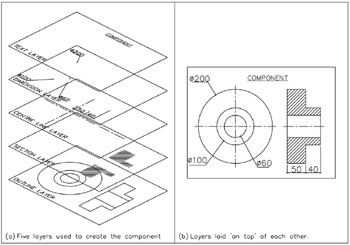
Figure 10.1: Layer concepts.
The following points are worth noting when considering layers:
all objects are drawn on layers
layers should be used for each 'part' of a drawing, i.e. dimensions should not be on the same layer as centre lines (for example)
new layers must be 'created' by the user, using the Layer Properties Manager dialogue...