Beginning AutoCAD 2006

Placing emphasis on learning by doing, this step-by-step guide provides a detailed exploration of AutoCAD functions required at each stage of producing a 2D drawing.
In this chapter we will investigate some additional draw and modify commands.
These commands will give the user some useful draughting tools.
Open your A3PAPER standard sheet with later OUT current.
Activate the Draw, Modify, Dimension and Object Snap toolbars.
Refer to Figure 21.1 and:
set the point style and size indicated with Format-Point Style from the menu bar
draw the following objects:
LINE from any suitable start point, to @85<15
CIRCLE with any suitable centre point and a radius of 30
POLYLINE with:
line segment from any suitable start point to @80,0
arc segment to @0, 50
line segment to @ 30,0
copy the three objects below the originals.
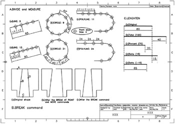
Figure 21.1: Using the DIVIDE, MEASURE, BREAK and LENGTHEN commands.
A selected object is 'divided' into an equal number of segments, the user specifying this number.
The current point style is 'placed' at the division points.
Menu bar with Draw-Point-Divide and:
| prompt | Select object to divide |
| respond | pick the line |
| prompt | Enter the number of segments or [Block] |
| enter | 5 |
| and | the line will be divided into five equal parts, and a point is placed at the end of each segment length as Figure 21.1A(a). |
At the command line enter DIVIDE
| prompt | Select object to divide |
| respond | pick the circle |
| prompt | Enter the number of segments or [Block] |
| enter | 9 |
| and | the circle will be divided into nine equal arc lengths and nine points placed on the circle circumference as Figure 21.1A(b). |