Beginning AutoCAD 2006

Placing emphasis on learning by doing, this step-by-step guide provides a detailed exploration of AutoCAD functions required at each stage of producing a 2D drawing.
Layers have allowed the user to display continuous, centre and hidden linetypes.
AutoCAD has the facility to display multilines and complex lines, these being defined as:
Multiline
Parallel lines which can consist of several linear elements of differing linetype and colour
They must be created by the user.
Complex
Lines which can be displayed containing text items and shapes
They can be created by the user
AutoCAD has several 'stored' complex linetypes.
Multilines consist of between 1 and 16 parallel line elements.
The ends of multilines can be capped with lines and arcs or be left uncapped.
The basic multiline terminology is displayed in Figure 27.1(a).
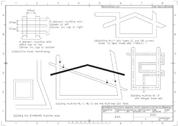
Figure 27.1: Multiline terminology and usage.
To investigate how to use multilines:
open your A3PAPER standard sheet with layer OUT current
refer to Figure 27.1.
From the menu bar select Draw-Multiline and:
| prompt | Current settings: Justification=Top, Scale=??, Style= STANDARD |
| then | Specify start point or [Justification/Scale/STyle] |
| enter | S |
| prompt | Enter mline scale |
| enter | 10 |
| prompt | Specify start point and enter 20,40 |
| prompt | Specify next point and enter @80,0 |
| prompt | Specify next point and enter @70<110 |
| prompt | Specify next point and enter @0,50 |
| prompt | Specify next point and right-click-Enter. |
Menu bar again with Draw-Multiline and:
set scale to 5
draw a square of side 40 from the point 20,60 using the close option Figure 27.1(b).
From the menu bar select Format-Multiline Style and:
| prompt | Multiline Style dialogue... |