Beginning AutoCAD 2006

Placing emphasis on learning by doing, this step-by-step guide provides a detailed exploration of AutoCAD functions required at each stage of producing a 2D drawing.
Up until now, all objects have been created:
by picking points on the screen
entering co-ordinate values
referencing existing objects, e.g. midpoint, endpoint, etc.
There are other methods which enable objects to be positioned on the screen, these being:
point filters
construction lines
ray lines.
Drawings contain information which may be useful to the user, including:
co-ordinate data
distances between points
area of shapes, etc.
In this chapter we will investigate several of the above concepts.
These allows objects to be positioned by referencing the X and Y co-ordinate values of existing objects.
Open the A3PAPER standard sheet and refer to Figure 19.1.
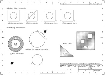
Figure 19.1: Point filters and drawing information exercises.
draw a 50-sided square, lower left corner at 20,220
ensure that grips are not active, i.e. off
multiple copy this square to three other positions.
A circle of diameter 30 has to be created at the 'centre' of each square and this will be achieved by four different methods:
Co-ordinates
Activate the circle command with centre: 45,245; radius: 15.
Object snap midpoint
draw in a diagonal of the square
select the CIRCLE icon from the Draw toolbar and:
centre point: Snap to Midpoint of diagonal
radius: enter 15
Object snap from
select the CIRCLE icon from the Draw toolbar and:
centre: pick the Snap from icon
base point: Endpoint icon and pick left end of line AB
offset: enter @25,25
radius: enter 15
Point filters
Activate the circle command and:
| prompt |