Rocker Switches Information
Last revised: February 7, 2025
Rocker switches are electrical switches actuated by a standard or dual rocker or paddle. They are available in different configurations including two-position On/Off, three-position, momentary, maintained and more.
Pole and Throw Configurations
SPST rocker switches make or break the connection of a single conductor in a single branch circuit. This switch type typically has two terminals and is referred to as a single-pole switch.
SPDT rocker switches make or break the connection of a single conductor with either of two other single conductors. These switches usually have three terminals and are commonly used in pairs. SPDT switches are sometimes called three-way switches.
DPST rocker switches make or break the connection of two circuit conductors in a single branch circuit. They usually have four terminals.
DPDT rocker switches make or break the connection of two conductors to two separate circuits. They usually have six terminals are available in both momentary and maintained contact versions.
A normally open (NO) rocker switch has contacts that are open or disconnected in their unactuated (normal) position. A normally closed (NC) rocker switch has contacts that are closed or connected in their unactuated (normal) position.
Switch Configurations
Maintained-contact rocker switches are described as:
- ON/OFF
- Three-position center-OFF
- Three-position no center-OFF
ON/OF rocker switches have separate ON and OFF functions and work like light switches. Three-position rocker switches have a center position that may or may not perform an OFF function.
Switch Functions
Momentary ON — describes contacts which interrupt the circuit when the rocker switch is in the normal, open (NO) position.
Momentary OFF — describes contacts which establish a circuit when the rocker switch is in the normal, closed (NC) position.
Alternate ON/OFF — describes a switch where the first actuation turns the rocker switch ON and the second actuation turns the rocker switch OFF.
Three-position momentary center-NEUTRAL rocker switches have a center position that can perform an OFF or NEUTRAL function.
Specifications
Important specifications for rocker switches include dimensions, electrical ratings, terminal types, materials and features.
Electrical Specifications
- Maximum current rating
- Maximum AC voltage
- Maximum DC voltage
- Maximum power rating
- Maximum mechanical life
Dimensional Specifications
- Length or diameter
- Width
- Panel thickness
Terminal Type
- Feed-through style
- Wire leads
- Solder terminals
- Screw terminals
- Quick connect or blade terminals
- Surface mount technology (SMT)
- Straight PC pins
- Right angle PC pins
- Side PC pins
Materials of Construction
Most rocker switch bases and rocker switch actuators are made of plastic, thermoplastic, or metal materials.
Features
- Pilot light or illumination
- Imprinted markings
- Wiping contacts
- Locking mechanism
- Time delay
- CE certification
- CSA certification
- UL listing
- Dustproof
- Weather resistant
- Waterproof
Standards
EIA-520D000 — This sectional specification relates to the toggle, paddle and rocker operated family of special-use electro-mechanical switches of certified quality.
MIL-S-22885/92 — This specification sheet is approved for use by Naval Electronic Systems Command, Department of the Navy, and is available for use by all Departments and Agencies of the Department of Defense.
Rocker Switches FAQs
What are the key differences between single-pole and double-pole rocker switches in terms of functionality?
The key differences between single-pole and double-pole rocker switches in terms of functionality are as follows:
Number of Circuits Controlled
Single-Pole Switches: These switches control a single circuit. They are typically used for simple on-off applications where only one circuit needs to be opened or closed.
Double-Pole Switches: These switches control two separate circuits simultaneously. They are used when two circuits need to be controlled with a single switch action.
Terminal Configuration
Single-Pole Switches: Generally have two terminals, which are the connection points for the single circuit they control.
Double-Pole Switches: Typically have four terminals, allowing them to connect and control two separate circuits.
Applications
Single-Pole Switches: Commonly used in basic applications like turning a light on or off.
Double-Pole Switches: Often used in more complex applications where two circuits need to be controlled, such as in industrial settings or for controlling two different power sources.
What are the different types of throw configurations for switches?
The different types of throw configurations for switches, particularly in the context of rocker switches, are as follows:
Single Throw (ST) Switches
These switches have two positions: open and closed. They control a single circuit by either connecting or disconnecting it.
Single Pole Single Throw (SPST): This is a simple on-off switch, like a basic light switch, which controls one circuit.
Double Throw (DT) Switches
These switches have two positions and can connect one input to one of two outputs.
Single Pole Double Throw (SPDT): This switch can connect a single input to one of two outputs, allowing for a changeover between two circuits.
Double Pole Double Throw (DPDT): This switch can control two separate circuits, allowing each to be connected to one of two outputs. It essentially functions as two SPDT switches operated by a single mechanism.
What are the applications of different throw configurations?
The applications of different throw configurations in rocker switches can vary based on the specific needs of the electrical circuit being controlled. Here's a breakdown of how these configurations are typically applied:
Single Throw (ST) Configurations
Single Pole Single Throw (SPST): This is a basic on-off switch used in simple applications like turning a light on or off. It is suitable for applications where only one circuit needs to be controlled.
Double Pole Single Throw (DPST): This configuration is used to control two circuits simultaneously with a single switch action. It is often applied in situations where two separate circuits need to be turned on or off at the same time, such as in certain industrial equipment.
Double Throw (DT) Configurations
Single Pole Double Throw (SPDT): This switch can connect a single input to one of two outputs, allowing for a changeover between two circuits. It is commonly used in applications where a device needs to switch between two different power sources or outputs.
Double Pole Double Throw (DPDT): This configuration can control two separate circuits, allowing each to be connected to one of two outputs. It functions like two SPDT switches operated by a single mechanism and is used in more complex applications, such as reversing the direction of a motor or switching between different operational modes in a device.
What are the advantages of using DPDT switches in industrial settings?
The advantages of using Double Pole Double Throw (DPDT) switches in industrial settings are primarily related to their versatility and ability to control multiple circuits. Here are some key advantages:
Control of Multiple Circuits
DPDT switches can make or break the connection of two conductors to two separate circuits. This capability allows them to control two independent circuits simultaneously, which is beneficial in complex industrial applications where multiple operations need to be coordinated.
Flexibility in Applications
These switches are available in both momentary and maintained contact versions, providing flexibility in how they can be used. For example, they can be wired as reversing switches for motors, which is useful in applications requiring directional control.
Isolation of Circuits
DPDT switches have six terminals, allowing for the isolation of circuits. This feature is particularly advantageous in applications with different voltages, as it ensures that the circuits remain isolated from each other, enhancing safety and reliability.
Versatility
The ability to switch between different operational modes or power sources makes DPDT switches versatile for various industrial applications, such as switching between backup and primary power supplies or changing operational modes in machinery.
Safety and Reliability
In industrial environments, safety is paramount. DPDT switches can be configured to ensure that circuits are safely disconnected when not in use, reducing the risk of electrical hazards.
What are the specific applications of DPDT switches in industrial equipment?
Double Pole Double Throw (DPDT) switches are versatile components used in various industrial applications due to their ability to control two separate circuits simultaneously. Here are some specific applications of DPDT switches in industrial equipment:
Motor Control
DPDT switches are commonly used as reversing switches for motors. This application is crucial in industrial settings where the direction of a motor needs to be changed, such as in conveyor systems or machinery that requires bidirectional movement.
Switching Between Power Sources
In industrial environments, DPDT switches can be used to switch between different power sources. This is particularly useful in scenarios where backup power systems are in place, ensuring continuous operation during power outages or maintenance.
Operational Mode Switching
DPDT switches allow for switching between different operational modes in machinery. This capability is beneficial in complex industrial equipment that requires different settings or modes for various tasks.
Circuit Isolation
The ability of DPDT switches to isolate circuits makes them suitable for applications involving different voltages. This feature enhances safety by preventing electrical interference between circuits.
Safety and Emergency Systems
In safety-critical applications, DPDT switches can be used to ensure that circuits are safely disconnected when not in use, reducing the risk of electrical hazards.
What are the advantages of using double throw switches in complex circuits?
The advantages of using double throw switches, such as Single Pole Double Throw (SPDT) and Double Pole Double Throw (DPDT) switches, in complex circuits are primarily related to their versatility and ability to manage multiple circuit paths. Here are some key advantages:
Versatility in Circuit Control
Double throw switches can connect a single input to one of two outputs, allowing for flexible control over circuit paths. This is particularly useful in applications where switching between different operational modes or power sources is required.
Complex Circuit Management
In complex circuits, double throw switches can simplify the design by reducing the number of switches needed to control multiple circuit paths. This can lead to more efficient and compact circuit designs.
Reversing and Changeover Applications
Double throw switches are ideal for applications that require reversing or changeover functions, such as motor direction control or switching between primary and backup systems.
Enhanced Safety and Reliability
By allowing for the isolation of circuits, double throw switches can enhance safety by preventing electrical interference and ensuring that circuits are safely disconnected when not in use.
Flexibility in Application
These switches are available in both momentary and maintained contact versions, providing flexibility in how they can be used across various applications, from industrial equipment to household appliances.
What are the differences between momentary and maintained contact versions of switches?
The differences between momentary and maintained contact versions of switches are primarily based on how they behave when actuated and released. Here's a detailed explanation:
Momentary Contact Switches
Action: These switches change their contact state only while being actuated. When the actuating force is removed, they return to their original state.
Example: A momentary switch is like a doorbell button, which only stays engaged while you are pressing it.
Applications: They are often used in applications where a temporary connection is needed, such as in push-to-talk communication devices or reset buttons.
Maintained Contact Switches
Action: These switches maintain their contact state even after the actuating force is removed. They stay in the new state until actuated again.
Example: A maintained switch is like a light switch, which stays in the on or off position until you flip it again.
Applications: They are used in applications where a stable, continuous connection is required, such as in power switches for appliances or machinery.
What are the safety considerations when using maintained contact switches?
When using maintained contact switches, there are several safety considerations to keep in mind to ensure proper and safe operation:
Circuit Isolation
Maintained contact switches can keep circuits in a connected state until manually reset. It's crucial to ensure that circuits are properly isolated to prevent unintended electrical interference or hazards.
Positive Opening Contacts
Positive opening contacts are a safety feature that ensures contacts remain open in the activated position even in the event of mechanical failure. This feature is often used in critical safety applications to enhance reliability.
Application Suitability
Ensure that the maintained contact switch is suitable for the specific application. For example, in applications where a continuous connection is required, such as power switches for machinery, maintained contact switches are appropriate. However, they should not be used in applications where a temporary connection is needed.
Mechanical Reset
Maintained contact switches require a mechanical action to reset the contacts. It is important to ensure that the reset mechanism is easily accessible and operable to prevent accidental or unintended activation.
Safety Protocols
Implement safety protocols to ensure that the switch is used correctly. This includes training personnel on the proper operation and maintenance of the switch to prevent misuse or accidents.
What are the differences between positive opening and regular maintained contact switches?
The differences between positive opening and regular maintained contact switches are primarily related to their operational reliability and safety features:
Regular Maintained Contact Switches
Action: These switches maintain their contact state even after the actuating force is removed. They stay in the new state until actuated again, requiring a mechanical action to reset the contacts.
Applications: They are used in applications where a stable, continuous connection is required, such as in power switches for appliances or machinery.
Safety Considerations: While they provide a stable connection, they do not inherently have additional safety mechanisms to ensure contact state in the event of mechanical failure.
Positive Opening Contact Switches
Action: Positive opening (or positive breaking) contacts are designed to remain open in the activated position even in the event of mechanical failure. This ensures that the contacts are reliably opened when required.
Applications: These switches are often used in critical safety applications due to their reliability, such as emergency stop buttons or safety interlocks.
Safety Features: The positive opening mechanism provides an additional layer of safety by ensuring that the contacts will open as intended, reducing the risk of electrical hazards in critical applications.
Rocker Switches Media Gallery
References
Electronics360— An engineer’s guide to foot switches
Electronics360—An engineers guide to foot switches
GlobalSpec—Rotary Limit Switches Information
Image credits:
C&K Components | Carling Technologies, Inc.
- CE Certified
- CSA Certified
- DPDT
- DPST
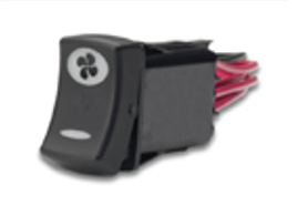
- Dual Rocker or Paddle
- Dustproof
- Feed-Through Style
- High Inrush Current Compatible
- Illuminated Switch
- Imprinted Markings
- Metallic
- Metallic
- Momentary OFF (Normally Closed)
- Momentary ON (Normally Open)
- ON / OFF
- Pilot Light
- Quick Connect / Blade
- Right Angle PC Pins
- RoHS Compliant
- SPDT
- SPST
- Screw Terminals
- Solder Terminals
- Standard Paddle
- Standard Rocker
- Straight PC Pins
- Thermoplastic / Plastic
- Thermoplastic / Plastic
- Three Position (Center OFF)
- Three Position (No Center OFF)
- Three Position Momentary (Center OFF)
- Three Position Momentary (Center ON)
- Time Delay
- UL listed
- Weather Resistant or Waterproof
- Wiping Contacts
- Wire Leads
- c h rocker switch
- italian rocker switch
- 3 position rocker switches
- 4 PST rocker switch
- high temperature rocker switch design
- rocker switch enclosure
- 72v DC rocker switch manufacturer
- 120V illuminated rocker switches
- 12v double rocker switches
- 15 amp rocker switches
- 15a 250vac rocker switches
- 16a 250V rocker switches
- 16a 250vac rocker switches
- 20a 250vac rocker switches
- 24 volt rocker switches
- 240 v rocker switches
- 4 pin rocker switches
- 4 pole rocker switches
- high temperature rocker switches
- hy26 rocker switches
- lighted SPST rocker switches
- low voltage rocker switches
- potentiometer rocker switches
- power strip rocker switches
- tracker boat rocker switches