AC Motors Information
 AC motors are electric motors which are powered by alternating current (AC). They are used to convert electrical energy into mechanical energy in order to do work in a system. Specifically, rotational energy is produced by utilizing the force of magnetic fields induced by alternating current flowing through electric coils. AC motors are used to provide power for a wide variety of systems, from small servomechanisms to large industrial machinery.
The majority of AC motors consist of two main components, a stator and a rotor. The stator is basically a metal ring with slots which hold coils of insulated wire containing a steel core. AC current runs through these wires to produce a rotating magnetic field. The rotor is a rod/shaft with a stack of evenly spaced conductor bars at its core. During operation the rotor core interacts with the magnetic field generated by the stator windings, causing the rotor to turn and produce torque. All these components are typically housed within a casing or enclosure designed to protect the motor and control heat generation. Motors also consist of a mount used to hold and stabilize the motor frame.
AC Motors vs. DC Motors
The key difference between AC motors and DC motors (besides the power source) is the method of speed control. In DC motors, speed varies based on the voltage applied; this relationship is relatively linear, making speed control and calculations simpler. In most AC motors, the speed is determined by the frequency of the power and adjusted using a variable frequency drive which changes the frequency of the supplied power. In general, AC motors are cheaper and more commonly preferred in fixed speed applications, while DC motors are often preferred for their simplicity when variable speed is required.
Types of AC Motors
There are two distinct types of AC motors, synchronous and induction.
Induction motors use shorted wire loops on a rotating armature and obtain their torque from currents 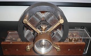 induced in these loops by the changing magnetic field produced in the field coils. In other words, voltage is ‘induced' in the rotor through electromagnetic induction, eliminating the need for brushed or slip ring commutation. The rotor in induction motors typically turns at a slower rate than the frequency supplied to it, and typically there is "slip" or loss of exact speed tracking during operation. Over 90% of all motors are AC induction motors because of their simplicity, rugged construction, and relatively low manufacturing costs. They are adaptable to many different environments and capable of providing considerable power as well as variable speed control.
Synchronous motors use a wound rotor, in which coils of wire are placed in the rotor slots. Since these 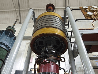 motors are excited by an external DC source, slip rings and brushes are used to supply current to the rotor. These motors are designed to operate at a specific constant speed, in step with the rotating magnetic field. A synchronous motor is not a self-starting motor because torque is only developed when running at synchronous speed; it can be started with a DC motor on a common shaft. A synchronous motor is often used where the exact speed of a motor must be maintained.
Other AC motor types are distinguished by specific features of design and operation, such as AC servomotors which utilize an encoder to provide precise position/speed feedback and control.
AC Power Requirements
The first step in AC motor selection is knowing the phase, voltage, frequency, and current of the AC power available for the application. AC motors are designed and rated for a certain type of AC power.
Frequency, as expressed in hertz (Hz) or cycles per second, indicates the frequency of the oscillations of alternating current. 50 Hz is the most commonly used worldwide, while North America uses 60 Hz. 400 Hz is a frequency used largely to power motors for aerospace applications.
Voltage, as expressed in volts alternating current (VAC), can be delivered at many different levels. 110 VAC and 220 VAC are typical residential and commercial voltages, while power between 460 and 600 VAC is common for larger industrial applications. A small variation in voltage can have a dramatic effect on motor performance. Insufficient voltage reduces torque output and can keep a motor from sustaining its rated speed, while excess voltage increases torque which can cause damage during startup.
|
Standardized Voltages and Frequencies |
|
|
50 Hz |
60 Hz |
|
380 VAC |
115 VAC |
|
400 VAC |
220 VAC |
|
415 VAC |
230 VAC |
|
220/380 VAC |
460 VAC |
Current, expressed in amps (A), describes the electrical current draw from motor at different points.
- Starting current, also referred to as locked rotor current, is the current draw when starting the motor. Starting current is always higher than full-load current.
- Full-load current indicates the current draw of the motor at its full rated output power.
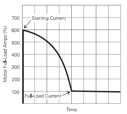
Current draw on a NEMA B motor. Figure Credit: Wermac Electric Ltd.
Phase describes the method of AC distribution.
Single-phase distribution, which involves one unison sinusoidal or other alternating voltage pattern, is used for standard commercial and residential power.
Three-phase power contains three simultaneous sinusoidal or other alternating voltage patterns, typically 120° out of phase with each other. Higher power efficiency and smoothness of operation is possible with three-phase operation. Three-phase power is most typically used for industrial or high power motors.
Performance Specifications
Another important factor when selecting AC motors is determining the performance specifications required for the application.
Speed (RPM) -- Motor speed refers to the rotational speed of the shaft at its rated voltage and horsepower, expressed in rotations per minute (rpm). In induction and reversible motors this value is fixed after construction, and requires a gearhead to be adjusted. If the motor is operated at less than full/rated load, the output speed will be slightly greater than the motor rating.
Torque -- The rotational force generated by the motor shaft. The torque required for the motor is determined by the speed-torque characteristics of the various loads experienced in the target application.
- Starting torque - The torque required when starting up the motor, which is typically higher than the continuous torque.
- Continuous torque - The output torque capability of the motor under constant running conditions.
Speed-torque performance curves, like the one shown below, are provided by manufacturers to detail the torque produced by the motor at its full range of shaft speeds, from starting to full-load.
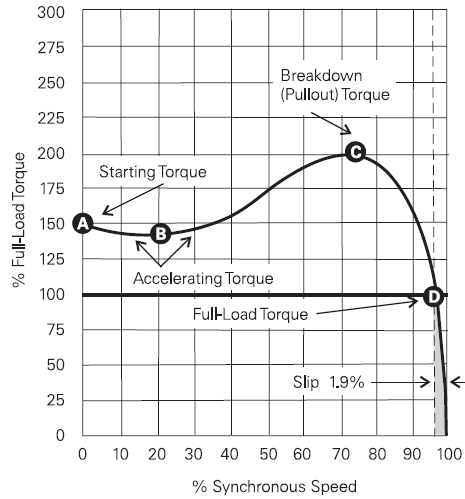
Speed-torque performance curve for a NEMA B induction motor. Figure Credit: Wermac Electric Ltd.
Horsepower -- The mechanical power output of the motor at rated speed and voltage, expressed in horsepower (hp). Horsepower is the product of shaft speed and torque, and is used as a gauge of the work output of the motor.
Efficiency -- Motor efficiency indicates the percentage of input electrical energy that is converted into output mechanical energy. Comparing two motors with the same horsepower, the one with higher efficiency will consume less power. Energy savings, lower operating temperature, longer life, and lower noise levels are common benefits of high efficiency motors.
Sizing and Construction
Sizing and construction parameters are an important part of AC motor selection.
Gearing
AC motors often have interchangeable or replaceable gearheads used for varying the unit's rated speed. Different types of gear designs provide varying characteristics and advantages.
Bevel -- Bevel gear sets have intersecting axes that are commonly, but not always, perpendicular. They mate via teeth on angled edges.
Harmonic -- Harmonic drives are extremely precise speed reduction systems, which transmit power via a rotating elliptical element that engages a flexible cup that then engages an internal gear, typically fixed. This power transmission delivers precise angular position in very high input-to-output ratio (50:1 & up) applications.
Planetary -- Planetary gearheads involve several gears per stage rather than one pinion-gear set. A "sun gear" drives multiple planet or satellite gears, which then mesh on the inside of an internal or annular gear to provide relatively high torque and power transmission ratings.
Spur -- Spur gearheads include one or more sets of pinion-gear sets, in which one pinion drives one gear. These sets can be stacked or cascaded to achieve higher reduction ratios.
Worm -- Worm gearing uses right-angled drives in which a worm drives a wheel coupled to the output shaft or shafts. This arrangement is used for high reduction and compact right-angle power transmission.
A number of other specialized types of gearing arrangements may also be available depending on the motor design and manufacturer. For more information on motor gearing, visit the Gearmotor Selection Guide on Engineering360.
Features
AC motors can be constructed with a number of internal operational features.
- Integral driver electronics are on-board, attached drivers or amplifier electronics.
- Integral brakes are used to stop motor rotation quickly, and may be mechanical or electronic.
- Integral clutches are used to engage and disengage the motor.
Size
Motor size is typically dependent on the performance of the unit, as larger motors with bigger components can generate more horsepower. However, sizing is critical in applications with strict space requirements. Motor dimensions may be specified in either English or Metric units. Dimensions to consider include:
- Diameter/width -- The diameter (cylindrical motors) or width (square/rectangular motors) of the motor body. This does not include flanges or additional components to the motor body.
- Housing length -- The length of the motor body, not including the shaft.
- NEMA frame size -- NEMA frame sizes conform to a standard size and mounting configuration identified by the National Electric Manufacturers Association (NEMA).
Environmental Parameters
There are a number of factors to consider relating to the environment in which the motor is operated.
Operating temperature(s) -- Specifies the rated temperature or range of temperatures that the motor is designed to operate at. Before a motor is started, its windings are at the temperature of the surrounding air (known as ambient temperature). Temperature in the motor will rise as soon as it is started. The combination of the ambient temperature and the allowed temperature rise equals the maximum winding temperature in the motor. Operating a motor in environments above the rated temperature will result in a derating of the motor continuous torque, while operating in extremely cold environments may require a different bearing lubrication.
Insulation rating -- The National Electrical Manufacturers Association (NEMA) has established insulation classes to meet motor temperature requirements found in different operating environments. The four insulation classes are A, B, F, and H. Class F is commonly used. Class A is seldom used. NEMA has standardized an ambient temperature of 40° C, or 104° F within a defined altitude range for all motor classes. Each insulation class has a specified allowable temperature rise.
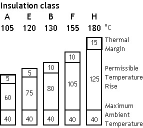
Image Credit: myElectrical
Shock rating -- Shock rating is the maximum shock the motor can stand and still meet operating specifications. Shock is expressed in units of acceleration (distance/time2), most commonly in g's as a multiple of the earth's standard acceleration due to gravity.
Vibration rating -- Vibration rating is the maximum vibration the motor can withstand and still meet operating specifications. Vibration is expressed in the same units as shock, based on acceleration.
Enclosure rating -- Enclosures are used to isolate motor components and protect them from the external environment. They are often rated or designed for different types of protection.
Dust-proof -- Dust-proof motors protect against dust infiltration with features such as total enclosure and labyrinth seals for shafts. The IP (Ingress Protection) rating for dust-proof motors is IP6x.
Drip-proof -- Drip-proof motors contain ventilation openings that are designed so that drops of liquid or solid particles falling from any angle within 15 degrees of vertical cannot enter the motor. Motors with an IP rating of IPx1 through IPx9 are considered drip-proof.
Explosion proof -- Explosion-proof motors have totally enclosed housings that are constructed to withstand internal explosion of a specified gas, vapor, or dust. Should such an explosion occur, the enclosure would prevent the ignition or explosion of the gas or vapor surrounding the motor enclosure. Several explosion-proof ratings are governed by Underwriter's Laboratories (UL).
Totally enclosed -- Totally enclosed motors have an enclosure that prevents free exchange of air between the inside and the outside of the enclosure. Common ratings are TEFC (fan-cooled) and TENV (non-ventilated); this is not an airtight rating. These motors are most frequently used in potentially contaminated environments.
Waterproof -- There are several degrees of waterproofing applicable to motors and they are reflected in the IP rating for the motor:
- IPx1 - Protection against vertically falling drops of water (drip-proof).
- IPx2 - Protection against direct sprays of water up to 15 degrees from vertical.
- IPx3 - Protection against direct sprays of water up to 60 degrees from vertical.
- IPx4 - Protection against water sprayed from all directions.
- IPx5 - Protected against low pressure jets of water from all directions.
- IPx6 - Protected against high pressure jets of water from all directions.
- IPx7 - Protected against the effects of immersion up to 1 meter.
- IPx8 - Protected against long periods of immersion under pressure.
Some motors may also be rated for use in special or extreme environments such as clean rooms, vacuum chambers, and cryogenic temperatures.
Standard NEMA Designs
The National Electrical Manufacturers Association (NEMA) provides standard motor designs with speed-torque characteristics designed to match various load requirements. The four standard NEMA designs are NEMA A, NEMA B, NEMA C, and NEMA D.
- NEMA A -- This design allows for higher starting currents and is used in applications with special load torque or load inertia requirements.
- NEMA B -- The most commonly used standard design, NEMA B motors develop approximately 150% of their full-load torque at startup.
- NEMA C -- Starting torque for this design is around 225% of full-load torque. This is important for hard-to-start applications such as plunger pumps, compressors, and loaded conveyors.
- NEMA D -- Starting torque for this design is nearly 280% of the motor's full-load torque. These are used for punch presses, cranes, hoists, and oil well pumps which require a very high starting torque.
Engineering Toolbox provides more information on the distinctions between these standard designs.
References
AC Motor Selection Form (pdf) - Applied Industrial Technologies
- Alabama
- Arkansas
- Arizona
- California
- Colorado
- Connecticut
- Florida
- Georgia
- Iowa
- Idaho
- Illinois
- Indiana
- Kansas
- Kentucky
- Louisiana
- Massachusetts
- Maryland
- Maine
- Michigan
- Minnesota
- Missouri
- Mississippi
- Montana
- North Carolina
- Nebraska
- New Hampshire
- New Jersey
- New Mexico
- Nevada
- New York
- Ohio
- Oklahoma
- Oregon
- Pennsylvania
- Rhode Island
- South Carolina
- South Dakota
- Tennessee
- Texas
- Utah
- Virginia
- Washington
- Wisconsin
- West Virginia
- 1 HP
- 1/2 HP
- 1/4 HP
- 115 / 120V 60 Hz
- 2 HP
- 208-230 / 240V 60 Hz
- 300 W
- 400 Hz / Aerospace
- 460 / 480V 60 Hz
- 5 HP / 3.6 KW
- 50 Hz / International Power
- 575 / 600V 60 Hz
- Bevel
- Brushless
- Cylindrical Body
- Double-ended
- Drip-proof
- Dust-proof
- English
- Explosion-proof
- Geared
- Hollow
- In-line
- Induction
- Integral Brake
- Integral Encoder
- Metric
- Multi-speed
- Offset / Parallel
- Open Frame / Frameless
- Planetary
- Reversible
- Right Angle
- Single-ended
- Single-phase
- Spur
- Square Body
- Synchronous
- Three-phase
- Torque Motor
- Totally Enclosed
- Universal
- Waterproof
- Worm
- exhaust fan motor
- blower motor replacement
- 3 phase induction motor
- 24vac motor
- miniature motors
- universal motor
- fan motor schematic diagram
- winch motor
- motor redmond
- hollow shaft motor
- synchronous 1 RPM clock motor
- low RPM motor
- minertia motor
- small AC synchronous motor
- small reversible motor
- 12 volt reversible motor
- 12v motor
- 12v synchronous motor
- 24 volt synchron motor
- explosion proof motor
- frameless motor
- split phase motor
- 3 phase motor schematic
- AC commutator motor
- hysteresis synchronous motor
- motor von weise
- synchronous motor animation
- three phase synchronous motor
- clock pinion wire
- parts and function of AC motor
