Power Transformers Information
Last revised: November 24, 2024
Reviewed by: Scott Orlosky, consulting engineer
Power transformers convert power-level voltages, as opposed to electrical signals, from one level or phase configuration to another. They are used to increase or decrease voltage to suit a specific application, and are widely used in electrical power distribution systems. For basic information about a transformer's construction and operation, please visit Engineering 360's Transformers Selection Guide.
Figure 1 shows a typical power distribution system. Because power plants must ultimately provide electrical power to potentially remote locations, they generate high voltages to transmit the current to these areas. Multiple power transformers must be incorporated into the system in order to gradually step down the voltage for safe residential use. Transformers may be used in the following ways:
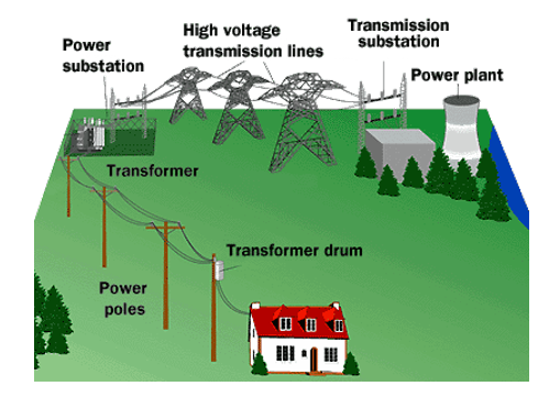
- Step down voltage from 500 kV long distance transmission to 69 kV localized transmission
- Further reduce transmission voltage to12 kV distribution voltage at a substation
- Reduce and condition distribution voltage to 110/220 V residential or commercial service, usually at 60 Hz.
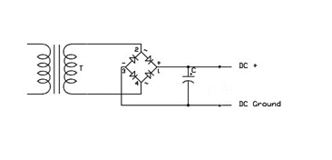
While most consumers are familiar with the transformer drums found on power line poles, power transformers represent a large variety of products suited to various applications. For example, alternating current (AC) adapters, also known as wall warts or plug packs, are simple rectifier transformers that convert AC mains electricity to lower voltage direct current (DC) for use with handheld devices. Figure 2 shows a schematic diagram and DC output of a very simple AC adapter. The power transformer is the coiled diagram at left, while the rectifier is the diamond shape in the center.
Types of Power Transformers
Power transformers may be classified into several different types based on the device's construction and application. Common types include autotransformers, isolation transformers, flyback transformers, distribution transformers, and substation transformers.
Autotransformers vs. Isolation Transformers
Autotransformers are constructed with only one wound coil and can produce various selectable output voltages from a single input voltage. The single coil acts as both the primary and secondary coil, with the output voltage depending on where electrical connections on the coil are made. Autotransformers do not provide electrical isolation, but are smaller, lighter, and cheaper than dual winding transformers. These devices are often used to step voltages up from 220-240 V to 110-120 V for residential use.
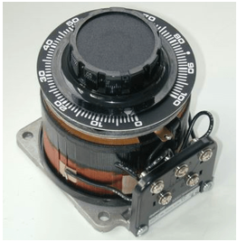
Variable autotransformers (or variacs) provide adjustable output voltage by making an electrical connection using a sliding brush. Variacs are often fitted with adjustable control knobs and allow for very smooth voltage control.
Isolation transformers contrast with autotransformers in that they contain two distinct coils separated in such a way that they provide electrical isolation between coils. While isolation transformers may be used to step voltage up or down, they sometimes have two coils of equal windings, providing a one-to-one ratio and thus providing identical output voltage.
Single Phase vs. Three Phase
Single phase- and three phase transformers are designed for use in single phase and three phase AC systems, respectively. Three phase transformers contain six total coils (three primary and three secondary) in order to accommodate all three signals and maintain isolation.
Flyback Transformers
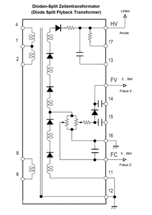
Flyback or line output transformers are specialized transformers originally designed to control cathode ray tubes (CRT) in televisions and monitors. Flyback transformers can sometimes be mistaken for specialized inductors in that, when input voltage is applied, current is stored in a magnetic core; when switched off, the secondary coil rapidly ramps up the output voltage, then safely ramps it down in a sawtooth wave (as opposed to the sine wave of the input voltage).
Unlike typical mains transformers designed to operate with 50-60 Hz AC, flyback transformers operate with switched currents at much higher frequencies, typically between 15 kHz and 50 kHz. In addition to their continued use with CRT devices, flyback transformers are used extensively in switched-mode power supplies and other wide-ranging applications.
Substation Transformers
Substation transformers are larger devices installed at power distribution substations. They are used to step voltage up or down for transmission purposes.
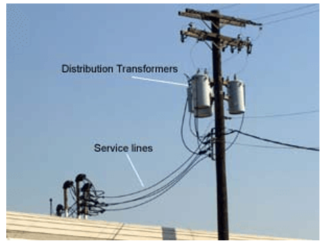
Distribution Transformers
Distribution transformers are pole-mounted devices that provide the final step-down action in a power distribution system. These devices supply relatively small amounts of power to residences and other locations connected to a power grid. They typically have high power and continuous voltage ratings.
Specifications
Electrical Specs
Buyers should consider important electrical specifications when selecting power transformers.
Power rating represents the rated power of the transformers secondary winding, in volts x amps (VA). Power rating is normally constrained by the transformer's cooling method; air, oil, and water are common cooling methods.
Maximum primary voltage represents the maximum input voltage range. Buyers should determine the maximum voltage needed for their specific application and search using this number. Because a transformer may feature more than one input voltage, a datasheet will specify the maximum as well as all additional input voltages.
Maximum secondary voltage specifies the maximum output voltage range; this range should be queried in the same manner as the maximum primary voltage.
Direct current resistance (DCR) is the resistance of the transformer measured in DC current. Transformer manufacturers attempt to design and manufacture in a way that minimizes DCR. Therefore it is usually specified as a maximum value.
Core Construction
Power transformers may be constructed using various types of core materials.
Laminated transformers contain laminated steel cores insulated with a nonconducting material to reduce electrical loss.
Split core transformers are constructed using a unique hinge and locking snap to allow electrical connection without interrupting the current-carrying wire. They provide a low cost method for monitoring current.
Toroidal core devices consist of copper wire wrapped around a cylindrical core, preventing the magnetic flux that occurs within the coil from leaking.
Power Transformers FAQs
Does a transformer have an inrush current?
Yes, a transformer has an inrush (starting) current around 12 times greater than the normal current through the transformer. This inrush normally lasts for about 15 cycles of the AC current, which means that one-quarter of a second after the transformer is started, the current will reach its normal value.
What is the arrangement of the windings in a transformer?
The insulation is installed around the core. The low-voltage winding is installed on the core insulation to reduce the voltage stress on the insulation. The high-voltage winding is installed around the low-voltage winding with spacers in between them to minimize the flux leakage in the transformer.
What are the losses in a transformer?
Transformers experience various types of losses, including core losses (hysteresis and eddy current losses) and copper losses (I²R losses in the windings).
What are the most important tests for oil in a transformer?
Important tests for oil in a transformer include dielectric breakdown voltage, moisture content, acidity, and dissolved gas analysis (DGA).
What is the purpose of the gas detector relay in a transformer?
The gas detector relay is used to detect the presence of gas in the transformer oil, which can indicate internal faults such as arcing or overheating. These faults decompose the oil and generate gases that dissolve in the oil or accumulate in the gas detector relay The gas detector operates by sensing the gas produced by these faults and triggering an alarm or protective action.
What are the methods of dealing with bad oil in a transformer?
Methods to deal with bad oil in a transformer include oil purification, degassing, and replacement. These processes help remove contaminants, moisture, and gases from the oil, restoring its insulating properties and extending the transformer's life.
What are the relationships between the input and output current and voltage of a transformer?
The relationship between the input and output current and voltage of a transformer is governed by the turns ratio of the windings. The voltage ratio between the primary and secondary windings is equal to the turns ratio, while the current ratio is inversely proportional to the turns ratio.
Why would the forces between the windings increase during a short circuit?
During a short circuit, the current through the windings increases significantly, leading to higher electromagnetic forces between the windings. These forces can cause mechanical stress and potential damage to the transformer.
What is the purpose of the unit service transformer (UST) and the station service transformer (SST)?
The UST and SST are used to supply auxiliary loads within a power plant. The UST typically supplies loads directly associated with the generating unit, while the SST supplies other auxiliary loads within the plant. This division helps ensure reliability and continuity of power supply to critical systems.
Power Transformers Media Gallery
References
GlobalSpec—Power Generation Handbook: Selection, Applications, Operation, and Maintenance
Jochen Kronjäger—The High Voltage Page
Image Credits:
HowStuffWorks | CNCCookbook | TipTemp | Wikimedia Commons | OSHA
- Alabama
- Arkansas
- Arizona
- California
- Colorado
- Connecticut
- Delaware
- Florida
- Georgia
- Iowa
- Idaho
- Illinois
- Indiana
- Kansas
- Kentucky
- Louisiana
- Massachusetts
- Maryland
- Michigan
- Minnesota
- Missouri
- Mississippi
- North Carolina
- New Hampshire
- New Jersey
- Nevada
- New York
- Ohio
- Oklahoma
- Oregon
- Pennsylvania
- Rhode Island
- South Carolina
- South Dakota
- Tennessee
- Texas
- Utah
- Virginia
- Washington
- Wisconsin
- 400 Hz
- 50 / 60 Hz
- 50 Hz
- 60 Hz
- AC
- ANSI
- Autotransformer
- Buck-Boost Transformer
- CSA
- Chassis Mount
- Chip Transformer
- DC
- Delta - Delta
- Delta - Single-Phase
- Delta - Wye (Y)
- Dish / Disk Mount
- Distribution Transformer
- Dry-type / Air Cooled
- Dual
- Electronics Transformer
- Encapsulated Coil
- Encapsulated Transformers
- Flyback Transformer (FBT)
- High-Voltage Transformer
- IEC
- Industrial Control Transformer
- Isolation Transformer
- Laminated Core
- MIL-STD
- Medical Transformer
- NEMA Enclosure
- Neutral Grounding Transformer
- Oil Filled
- Outdoor Use
- PC / PCB Mount
- Pad-Mounted
- Pole-Mounted
- Power Transformer
- Quad (2+2)
- Rectifier Transformer
- RoHS Compliant
- Single
- Single Phase Transformer
- Solar Power Transformer
- Split Core
- Substation Transformer
- TUV
- Three Phase / Polyphase Transformer
- Toroidal Core
- UL
- VDE
- Water
- Waterproof
- Wye (Y) - Delta
- Wye (Y) - Single Phase
- Wye (Y) - Wye (Y)
- amplifier power transformers
- substation power transformers
- 440v to 115v transformer
- power transformer insulation
- 480 volt to 208 volt transformer
- gs transformer
- xentek isolation transformer
- 100v to 115v transformer
- 115-kV power transformers
- 120 208 volt transformers
- 1200 to 8 ohm audio power transformer
- 1250-kVA power transformer
- 132-kV power transformer
- 230-kV power transformer
- 277 volt to 208 volt transformers
- 277v transformer 1kva
- 400-kVA power transformer
- 400v power transformer MTBF
- 480 volt to 240 volt transformer
- 8 ohm to 70 volt transformer
- afp transformer
- current transformer ammeter
- gs Heavy-Duty transformer
- IGBT ignition
- isolation transformer PCB
- miniature power transformers
- pad mount transformer dolly
- powertron transformer
- ritz transformer current
- 110 220V transformer