Control Valves Information

Control valves are power-operated devices used to automatically modify fluid flow or rate pressure in a process system. The terms 'control valve' and 'throttling valve' are often used interchangeably but there is a distinction between the two. A throttling valve is a valve whose closure element has the ability to start and stop flow as well as stop along any position of the valve stroke to regulate the process of flow, temperature or pressure. Control valves are the final control element in the system and are used in conjunction with an actuator or actuation system. Control valves cannot act as standalone valves and therefore, while all control valves are throttling valves, not all throttling valves are control valves.
Find Control Valves by Specification or See Our Directory of Suppliers
There are several key functions a control valve must fulfill in order to function properly. These functions include:
- No external leakage
- Adequate capacity for the system media
- Resistant to media characteristics (corrosive, high temperatures)
- Fits within the rest of the control assembly
Control valves are activated by a disruption in the control system. When the control system is disturbed, the valve will manipulate the flowing media to compensate and keep the regulated process variable close to the desired set point. These valves are used throughout industry in many applications. There are several important factors to consider when selecting a control valve for a system, including reasonable cost, maintenance, energy consumption, and compatibility with the control loop in addition to the items discussed below.
Types of Control Valves
Sub-assembly types have been developed to fulfill the functions according to the appropriate applications. There are several methods of control a valve can use. The most successful disc motions are linear and rotary.
Linear Motion
Linear motion valves have a disc which moves perpendicular to the flow.
Globe valves are linear motion valves with rounded bodies, from which their name is derived. They are widely used in industry to regulate fluid flow in both on/off and throttling service. Globe valve bodies are highly efficient control valves and can be adapted to a wide variety of applications.
Rotary Motion
Rotary motion valves have a disc which swings or turns to adjust the flow through the valve.
Butterfly valves are quick opening valves that consist of a metal circular disc or vane with its pivot axes at right angles to the direction of flow in the pipe. When rotated on a shaft, the disc seals against seats in the valve body. They are normally used as throttling valves to control flow.
Ball valves provide tight shut-off and control. They have high rangeability due to the design of the regulating element, without the complications of side loads typical of butterfly or globe valves.
Plug control valves, also called cock or stop-cock valves, remain one of the most widely used valves for both on/off and throttling services. Plug valves combine many positive attributes of the globe, butterfly and ball valve. The valve has an offset plug which swings into a seat to close the valve. It is a rotary motion valve, which offers minimal breakout torque and tight shut off without excessive actuator power needed.
Media
Control valves can be used in a wide range of applications. When selecting a control valve it is important to consider the type of media the valve will contact. Media types include gases, liquids, and liquids with suspended solids. The material temperature is also important to consider. For corrosive or otherwise harsh chemicals select a valve with can withstand the media and not degrade the disc or body. For more information on the appropriate valve for a type of media, please read the Industrial Valves Selection Guide.
Control Valve Components
A control valve has two critical components; the valve body and the control valve actuator. For more information on valve components, please read the Industrial Valve Selection Guide.
Video Credit: Flowserveinteractive / CC BY-SA 4.0
Body Construction
The body of the control valve holds the media as it travels through the system. The body has inlets and outlets for the flow as well as the regulatory element of the valve type. The valve body contains the closure element and therefore must be able to permit actuator thrust transmission, be resistant to the effects of the media, and have the appropriate ends to ensure connection with the system and prevent any leaks. There are three body types which vary based on the number of ports.
Single port valve bodies are the most common control valve design. The design is available in various forms such as globe, angle, bar stock, forged and split constructions. They can be specified for a wide range of applications and are generally used in situations with stringent shut off requirements. Metal-to-metal seating surfaces can handle most services requirements. This 'soft-seating' is achieved with nitril or other elastomeric materials forming the seal. When used in high pressure applications, the fluid pressure loads the entire area of the port. The unbalanced forced created is important to consider when selecting an actuator for the system; the actuator should aid in regulating the media to achieve laminar flow. Generally single port valve bodies are small and use cage style construction to hold the seat ring.
Double-port valve bodies used for throttling restrict the fluid passing through them. They can be used as a throttling valve because it is easy to position them to control the flow. Double-port systems can be used for liquid media of varying temperatures and are best used when there is a large capacity that must be passed using a large valve.
Three-port valves can be used to mix or divert liquid passing through them. They maintain a balance across the distribution system. Three-port valves can be found in piston valves, globe plug valves, and rotating shoe type valves.
Control valve bodies can be customized for specific services.
Seat Configuration
Seat features include metal-to-metal, O-ring or soft seat, Class IV or V, and Class VI. Cage style trim holds the seat ring, provides guidance for the valve plug and allows for particular flow characteristics. They are easy to maintain and flexible enough to change flow characteristics such as reduced capacity flow, noise attenuation, or elimination of cavitation.
Design Tip: Components built as an assembly generally lead the best dynamic performance.
Actuator
Actuators provide the force necessary to move the control valve. Most common control valve actuators are pneumatically operated, but other actuators such as electric, hydraulic, and manual are also available.
Manual/ hand operated actuators use a hand-wheel or crank to open or close the valve. They are not automatic but offer the user the ability to position the valve as needed. Manual actuators are used in remote systems that may not have access to power, however they are not practical for applications that involve large valves.
Solenoid operated valves use hydraulic fluid for automatic control of valve opening or closing. Manual valves can also be used, with a solenoid valve, for controlling the hydraulic fluid; thus providing semi-automatic operation. A solenoid is a designed electromagnet. When an electric current is applied, a magnetic field is generated around the wire. An iron "T" or plunger is put in the center of the coil to concentrate the magnetism and the "T" is drawn by the magnetic field into a position where the magnetism can travel 100% through the metal conductor. The moveable "T" acts as the actuator of the valve. Solenoid valves can be arranged such that power to the solenoid either opens or closes the valve. One application of solenoid valves is to supply the air to systems like pneumatic valve actuators. These valves are not practical for large systems because their size and power requirements would be excessive.
Pneumatic operated valves can be automatic or semi-automatic. They function by translating an air signal into valve stem motion by air pressure acting on a diaphragm or piston connected to the stem. Pneumatic actuators are fast-acting for use in throttle valves and for open-close positioning. They are simple, dependable and direct acting. They can be used in demanding conditions because of their integral positioner capability and high stem force output.
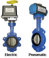
Image Credit: Dwyer
Hydraulic actuators provide for semi-automatic or automatic positioning of the valve. They are used when a large force is required to open the valve, such as a main steam valve. With no fluid pressure, the spring force holds the valve in the closed position. Fluid enters the chamber, changing the pressure. When the force of the hydraulic fluid is greater than the spring force, the piston moves upward and valve opens. To close the valve, hydraulic fluid (such as water or oil) is fed to either side of the piston while the other side is drained or bled. Hydraulic actuators are available in a wide range of sizes and are economical to use in a valve system as well as with a single valve.
Electric motor actuators permit manual, semi-automatic, and automatic operation of the valve. The high speed motor is usually reversible and used for open and close functions. The actuator is operated either by the position of the valve or by the torque of the motor. A limit switch can be included to automatically stop the motor at fully open and fully closed. Electric and electro-hydraulic actuators are more expensive but they can be used in places where there is no air supply, where low ambient temperatures could freeze condensed water in pneumatic supply lines, or where unusually large stem forces are needed.
End Configuration
There are many choices for end configuration on control valves. The end configuration can be chosen based on compatibility with the preexisting system and the leakage protection needed.
Materials
When choosing a material for the control valve consider the parts which must retain close machine tolerances for sealing, metering or moving. The material for these parts must be resistant to corrosion, erosion and distortion. The body is less affected by the media. Metal material choices for valve body include brass, bronze, copper, cast iron, ductile iron, Monel, stainless steel and steel. Plastic material choices include PVC and CPVC.
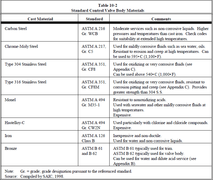
Chart Credit: US Army Corps of Engineers
Find Control Valves by Specification or See Our Directory of Suppliers
Performance Specifications
Important specifications to consider when searching for power-operated control valves include dead band, leakage rates, flow characteristics, pressure drop and valve sizing.
Dead Band
Dead band is a phenomenon where a wide range or band of controller output (CO) values fails to produce a change in the measured process variable (PV) when the system reverses directions. This means that when there is a change in the system the controller attempts to adjust for the change so the flow remains the same. The adjustment must be big enough to register with the valve; it must pass through the dead band. If the adjustment stays in or under the dead band the system will not compensate for the change. The dead band is a major contributor to process variability. The valve can be a source of this variety due to friction, backlash, shaft wind-up, relay or spool valve dead zone. The dead band is needed in the system because it ensures that the process variable deviation from the set point will be big enough to get through the dead band and correct the problem. The common causes of dead band are friction and backlash in the control valve, along with shaft wind-up in rotary valves.
Selection Tip: A well-made valve should respond to signals of 1% or less to provide effective reduction in process variability.
Leakage Rates
Control valve leakage is defined as how much media the valve will leak when it's fully closed. There are various standards to assess leakage, including the British Standard which can be seen in the chart below. Generally, the lower the leakage rate the higher the cost so it's important to identify the needs of the control system.
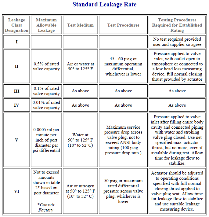
Chart Credit: Process Development & Control, Inc.
Flow Characteristics
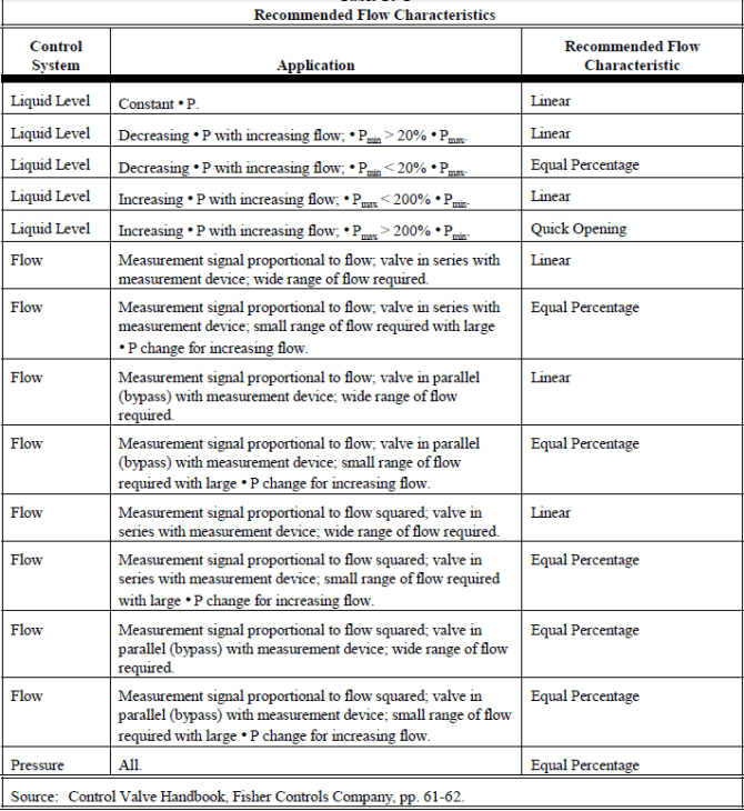
Flow characteristics describe the relationship between control valve capacity and valve stem travel. Trim describes the shape of the plug and seat arrangement. This arrangement affects the capacity changes as the valve moves. Many valves do not have linear flow because of the many differences in trim design. Therefore, valve trims are designed to suit the application needs and adjust for the inherent non-linearity in many control loops. The curves are based on constant pressure drop across the valve and graphs are usually available through the manufacture. There are six inherent control valve characteristics, all shown in the graph below. The chart is plotted stem opening % vs. flow %. The stem opening describes how much the valve is open. In this context, valve opening refers to the position of the disc to the closed seat position. The three most common flow characteristics are linear, equal-percentage or modified flow.
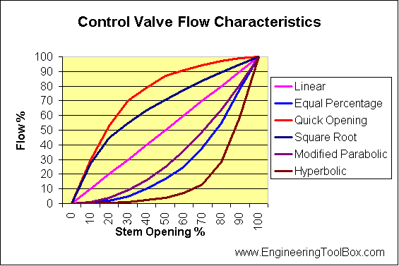
Linear- The flow rate is directly proportional to the amount the disc travels. If the disc is open 50%, the flow rate is at 50% of maximum flow. Linear valves are best used for water systems.
Equal percentage- The flow rate is related to the percent the valve opening changed in an incremental manner. For example, if the valve changed from 20% open to 30% open and produced a 70% change in flow rate, changing the valve from 30% to 40% open would increase the flow rate another 70%. Equal percentage valves are best used for steam applications.
Modified parabolic- This flow rate is approximately midway between linear and equal-percentage characteristics. Modified flow offers fine throttling at low capacity and close to linear characteristics at higher capacity.
When choosing a flow characteristic, consider the direct relationship between valve opening and flow over as much of the travel of the valve as possible.
Valves can also have installed flow characteristics when the valve is installed into a control system with pumps, piping, and fittings, causing the pressure drop to vary. The control system components alter the flow rate so it is no longer determined by the geometry of the valve body and disc. The flow rate is altered by resistances resulting from pipelines, orifices, or other equipment in series with the control valve. For a linear valve, the effect may be described by the following equation.
Q = L / [α + ( 1 - α) L2]1/2
Where:
Q= volumetric flow rate
L= length of stem travel
α= ratio of valve head differential at max flow to zero flow
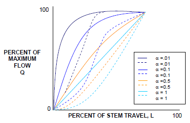
Installed flow characteristic for linear control valve installed in flow systems having a different valve of α. Chart Credit: KLM Technology Group
Selection Tip: The best choice is usually a linear valve and because they tend to be used most often, the installed and inherent characteristics are similar and linear. Therefore, there will be limited gain in the control loop. Equal percentage valves will also provide good results and are tolerant of over-sizing.
Valve Sizing
Sizing is critical when selecting a control valve. There are several variables to consider when determining sizing for a valve. First is what type of media the valve will be controlling. The specific gravity and viscosity of the media will affect flow rate. Second is the maximum inlet pressure and temperature, along with the outlet pressure (pressure drop) at maximum load. Third is the maximum capacity and last is the maximum pressure drop the valve must close against.
The media the control valve will be handling is important to consider when sizing a valve because the specific gravity and viscosity of the media can alter the flow rate. Control valves can be used for liquid, gas or a mixture of the two. Using principals established by Bernoulli, the square of the flow velocity is directly proportional to the pressure differential across the orifice and inversely proportional to the specific gravity of the fluid as seen in the equation below.
Q= Cv* ( ΔP ÷ S)
Where:
Q= Flow of fluid in gallons per minute
Cv= Valve sizing coefficient determined experimentally for each style and size of valve, using water at standard conditions.
ΔP= Pressure differential across the valve in psi
S= Specific gravity of fluid (Water at 15.56°C = 1.00)
Based on this equation, the greater the pressure differential across two points, the greater the velocity of fluid flow across two points. In addition, with greater density, there will be a lower velocity of flow.
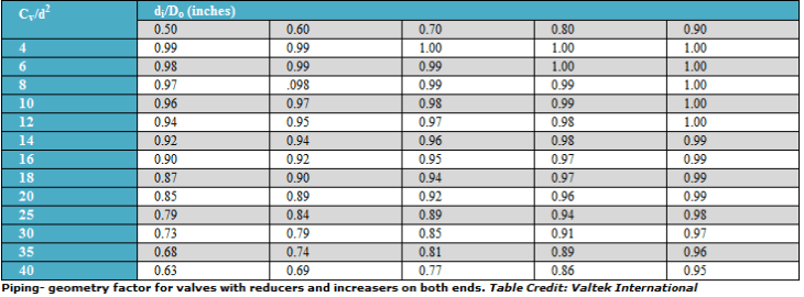
The piping geometry factor accounts for the reduction in the effective flow rate of the valve due to reduction in the pipe size. It is a dimensionless factor that accounts for the difference in piping at the inlet and outlet. The pipe geometry factor can be adjusted by using the chart below. The piping geometry factor, (Fp), is described by the inside diameter of the pipe is (di) and the outside diameter (Do).
Find Control Valves by Specification or See Our Directory of Suppliers
Standards
Control valves may configure to ANSI standards, API standards, MSS specifications, UL listings, ASME standards, and Federal specification WW-V-35C. Check with manufacturer for exact listings. Some control valves may come configured as a multi-piece design.
Applications
Common applications for control valves include general purpose, process control, oil or fuel, sanitary, waste water, water, irrigation, gas or air, steam, fire service, cryogenic, refrigeration, chemicals, and laboratory or medical.
Resources
Control Valves and Flow Characteristics
PDHEngineering- Valve Fundamentals
Skousen, Philip L. Valve Handbook. New York: McGraw-Hill, 1998. Print.
Image Credit: AZCO | Badger Meter | Co-ax valves
- Alabama
- Arizona
- California
- Colorado
- Connecticut
- Florida
- Georgia
- Hawaii
- Iowa
- Illinois
- Indiana
- Kansas
- Kentucky
- Louisiana
- Massachusetts
- Maryland
- Michigan
- Minnesota
- Missouri
- North Carolina
- North Dakota
- Nebraska
- New Hampshire
- New Jersey
- New Mexico
- Nevada
- New York
- Ohio
- Oklahoma
- Oregon
- Pennsylvania
- Rhode Island
- South Carolina
- Tennessee
- Texas
- Utah
- Virginia
- Washington
- Wisconsin
- API
- ASME
- Acetal
- Air
- Aluminum
- Balancing Valves
- Ball Valves
- Bellows Valves
- Bolt Flange
- Brass / Bronze
- Butt Weld
- Butterfly Valves
- CPVC
- Cartridge / Manifold Valves
- Cast Iron
- Clamp Flange
- Cold Water
- Compressed Air
- Compression Fitting
- Copper
- Cryogenic Valves
- DIN
- Diaphragm Valves
- Directional Valves
- Diverter Valves
- Drain Valves
- Ductile Iron
- Electric
- Electro-hydraulic
- Electro-pneumatic
- Exotic Metal
- Fire Service
- Gas
- Gasoline / Diesel Fuel
- Gate / Knife Valves
- Globe Valves
- Ground Water
- High Purity Gas
- Hot Water
- Hydraulic Fluid
- ISO
- Intrinsically Safe
- LP - Gas
- Metal Seated
- Mixing Valves
- NSF
- Natural Gas
- Needle Valves
- Nylon - Polyamide
- PEEK
- PTFE - Teflon®
- PVC
- PVDF
- Pinch Valves
- Plug Valves
- Pneumatic
- Polypropylene (PP)
- Poppet Valves
- Potable Water
- Powder / Solids
- Pressure Relief Valves
- Salt Water
- Sanitary / Hygienic Valves
- Servo Valves
- Severe Service Rated
- Socket Weld / Solder
- Solenoid Valves
- Sour Gas
- Specialty / Corrosive Gases
- Spool Valves
- Stainless Steel
- Steam
- Steel
- Thermally Actuated
- Threaded
- Toggle Valves
- Tube Fitting
- Union
- Wastewater
- Water
- flow control valve
- post indicator valve
- directional control valve
- control valve assembly
- level control valve
- remote control valve
- ITT grinnell valve co
- furnace gas control valve
- brake pressure control valve
- flow control valve sizing
- vent control valve
- CO2 control valve
- control valves for natural gas
- mixing control valve
- proportional valve driver
- temperature control valve
- 12 volt water valve
- 3 way rotary valve
- automatic control valve
- dynaflow valve control
- float control valve
- flow control valve gpm
- honeywell l8148e control
- hot water control valve
- hydraulic directional control valve
- hydraulic flow control valve
- mini flow control valves
- pressure independent control valve
- throttle control valve
- throttle plate
